You will Need to do this with a DashBoard Custom Panel.
Create a New Custom Panel
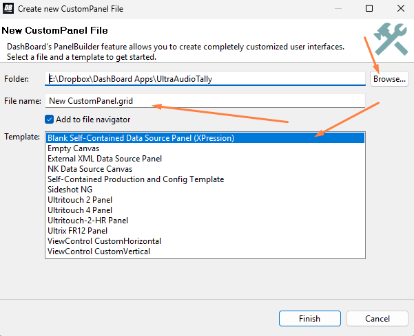
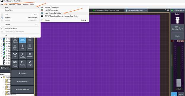 Select where you want to save it, the Name and the self contained data source type:
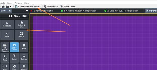
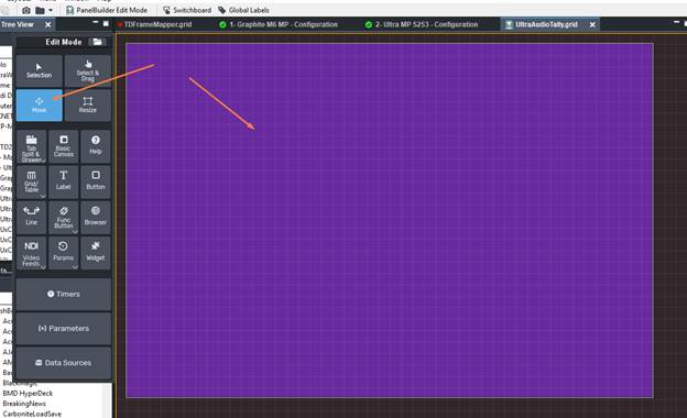
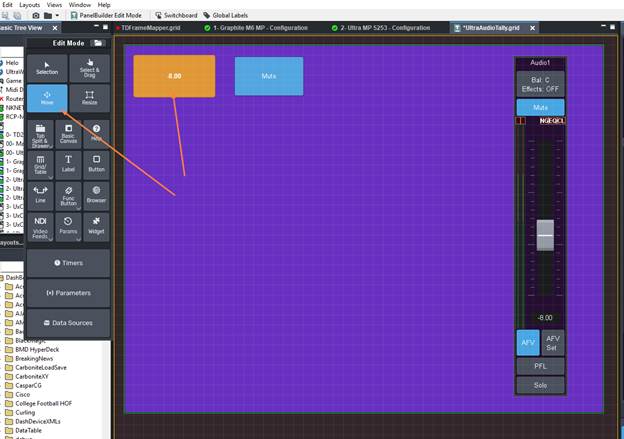
You enter Panel Builder mode using CTRL+G or by clicking on the button in the tool bar - note you get the edit mode tool bar on the left:
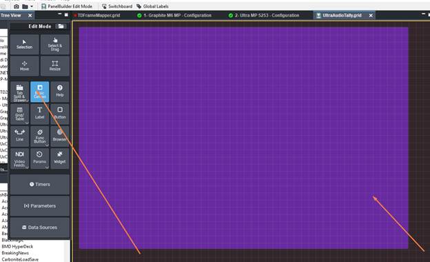
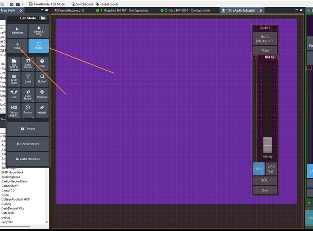
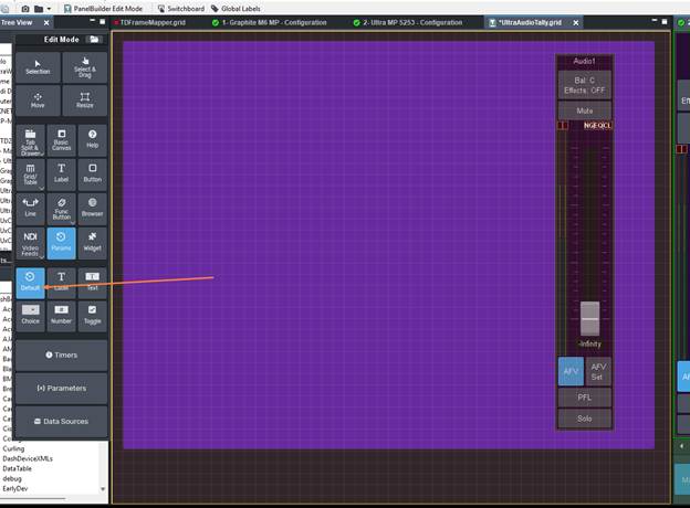
Make a Basic Canvas so that we have a place to Drag and drop the Fader to and so we can maintain the device context. When you draw it you will be left with a blank transparent back ground not the Purple you see here..
Switch back to the Selection or Move Tool and then double Click on the canvas you just made:
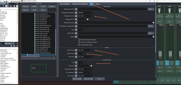
Anything you Modify will end up at the top. Unused Style elements will be found in their sections.
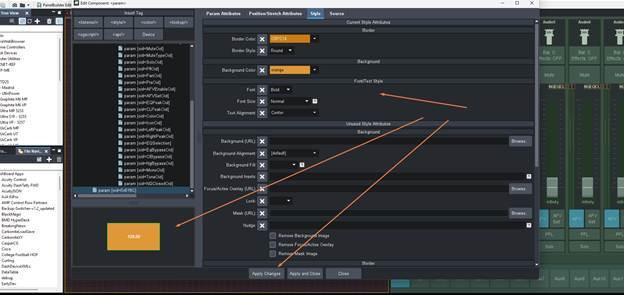
I changed the Background colour and then also gave it a border and border style. So you won't see them exactly in the same spot and will need to scroll down the appropriate sections:
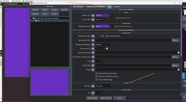
Once set hit Apply and Close
We Need to make the ABS get the Context of the Carbonite Switcher. To do this we need to make sure That we Drag in something to that ABS – Make sure it is selected then go to the Live Assist ME tab on Carbonite and press CTRL+G to put it into edit mode so you can select the component.
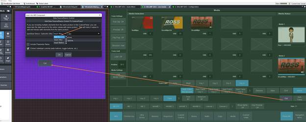
Make sure that you select the "ADD TO" abs so that it will add this context for you. This is needed for keeping the Parms relative to the device when it goes to look for them. We will delete this later when we have the Data sorted.
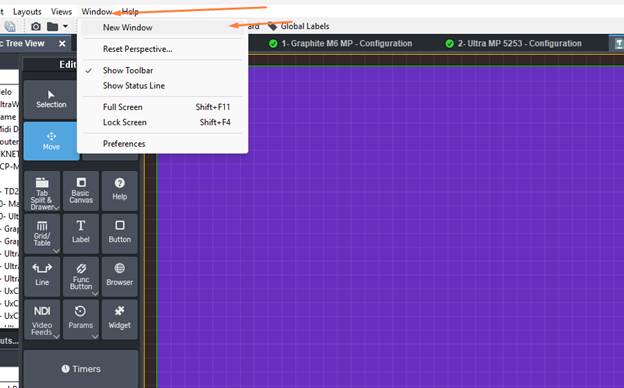
Then we can open the audio mixer tab and drag it too the Right side so that we have them side by side ...
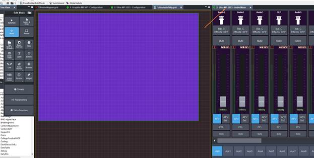
or if you have separate screens you can also launch a new dashboard window instead and then open the audio mixer there.
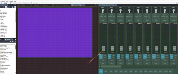
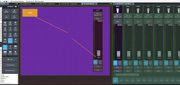
Now that we have the Audio Mixer Tab open -- we can see the channel we would like to work with on the correct mixer (for this example I will use Channel 1 on Main Mixer) We what to click on that tab or window and press CTRL+G so that the Audio Mixer Tab is also put into Edit mode (note that you can not directly edit in the pages served up by the switcher -- this is just used to enable Drag and Drop Mode -- there will be a "tint" that covers the panel to signify Edit mode is active:
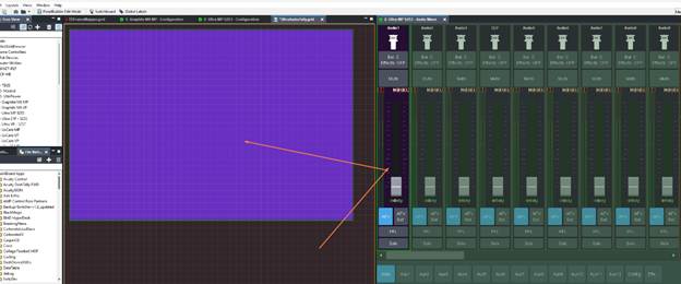
We will now Click on the Fader Strip and Drag it to the Left to (Make sure that the Canvas was last click on in the custom Panel so that is the "focus" and is going to be where the Channel strip is trying to be dropped -- we want to make sure the Canvas will become the Switcher Context for Data.
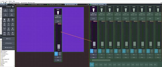
Then we can position and Size it how we like:
Now we can use the Context to also extract just the elements that we need. We will need the Mute Button and the Volume Control.
Note we can use CTRL+I to enable Inspector Mode to figure out the OIDs as well:
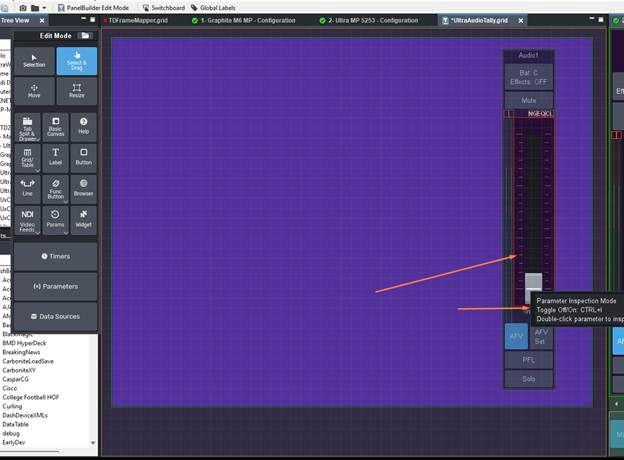
Here we can see the individual items that make up the Strip. So we want the Volume Fader and the Mute Button:
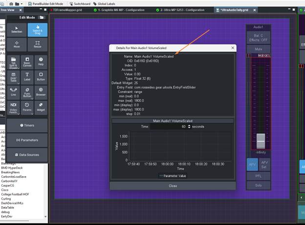
We can take the Scaled or the Non Scaled version -- either will be fine. however I will end up going for 0x618C which is the non Scaled version so we will see the values that the Label under the fader uses.
For the Mute Button we see it is 0c618F
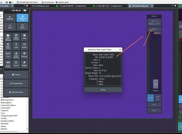
Press CTRL+I again to leave Inspector Mode.
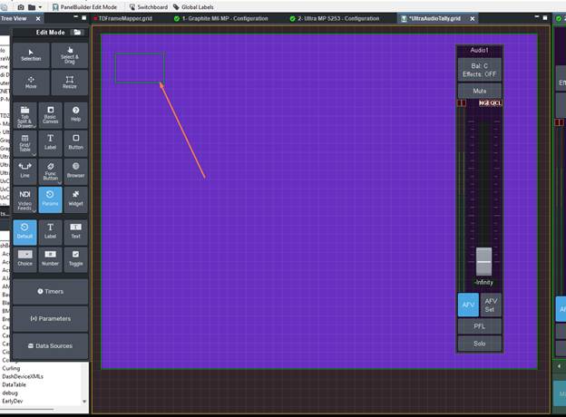
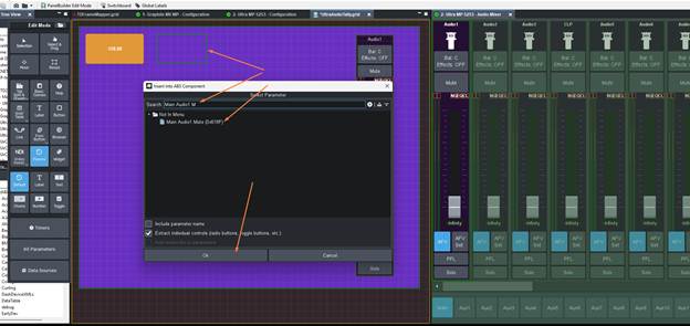
Now lets grab the Parm Edit tool and Draw where we want the Value to be displayed. We need to use the Default sub type.
Now we Draw the box (don't worry you can edit the style and size after if it's too small.
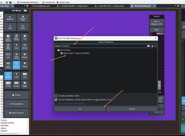
When the Select Parm opens up we can then search based on the 0x618C value or we could just type in Main Audio1 Volume to sort the list quickly.
Select it and press Okay
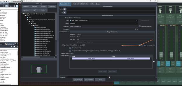
Now switch back to the Move or Selection Tool and Double click on the "fader"
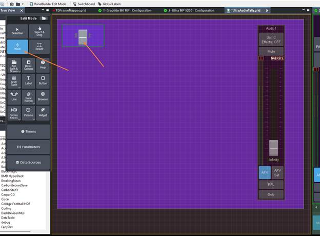
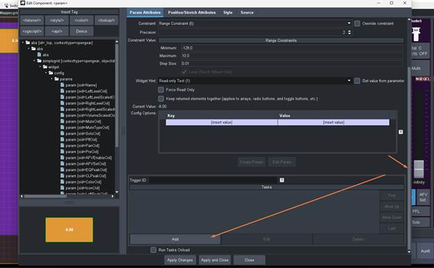
Now we will un check the Get Value from Parameter and then set it to a label
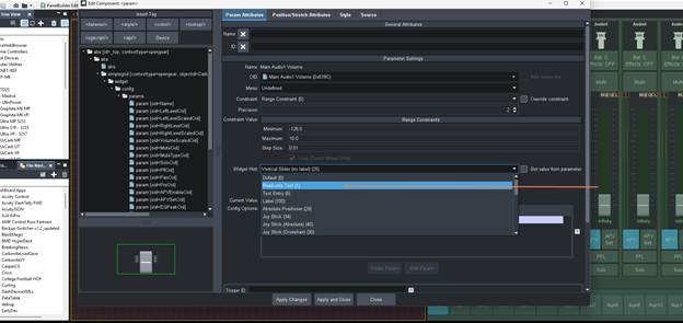
Hit Apply Changes and then you can go to the Style Tab and adjust the style of the Label and see it on the Left of the viewer
Now hit Apply and Close
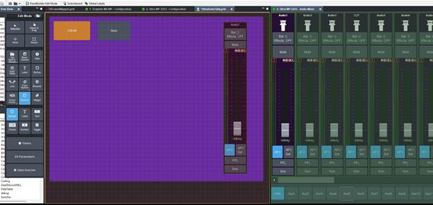
We Now have the Parameter in our panel and ready to attach some Logic to it. We will need to do the same for the Mute Button so that we can make it that if either fader is moved or the Mute button is uses both Data Values will trigger the logic.
So use the exact same steps but look for the Mute Parm:
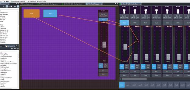
There we go .. Now we have the Mute Button and the Fader Volume Value in our Panel:
And you can see any control from the Ultra will be seen by this panel:
So now lets go ahead and we can setup some Logic on the Volume Value first:
Switch back to the Selection or Move Tool and double click on the Volume Label we made:
On the Right Side make sure to scroll down and then select the ADD button in the TASKs Section:
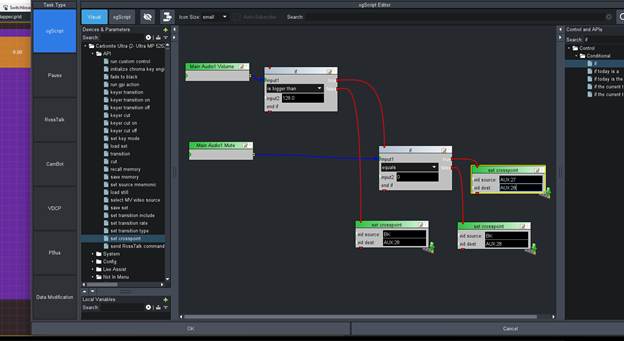
We are now going to build out some logic using the Visual Logic in the ogScript section.
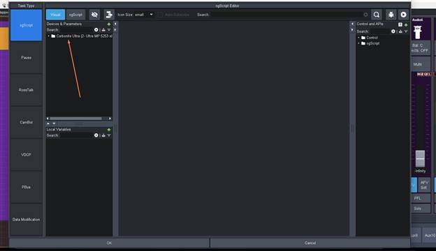
Now let's search for the Audio Parameters we need to use
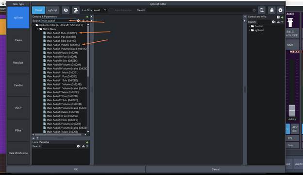
We can then Drag or double click on the two Parameters we are going to need:
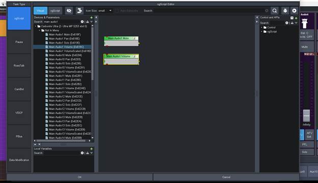
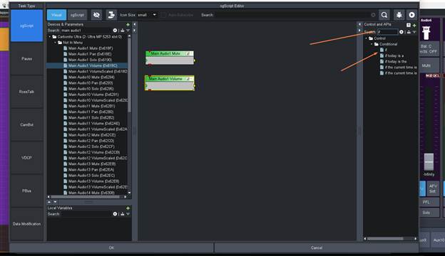
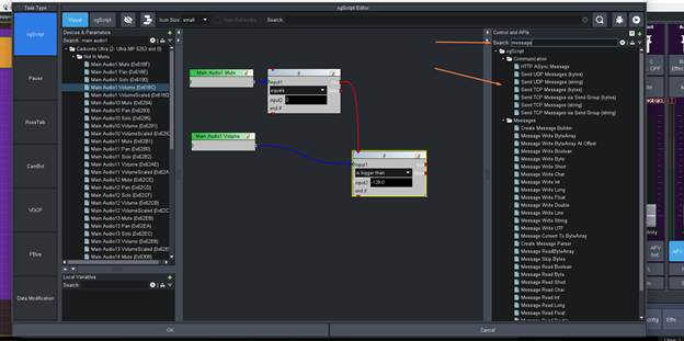
Now on the Right Side we can go into the Controls and API side of things are get some "if" blocks
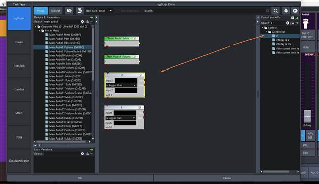
You can then drag them around to align them how you like and then hook up the Data Inputs into them.
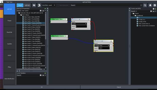
This will make sure that if the Mute is OFF and the Value changes to be greater than "infinity" where that value is -128.0 we can then have the True Output Send a Function. I will also add two False Functions as to what to do if that is move and those are not valid – ie when it gets back to infinity it would send an event via the FALSE path to turn off the Light.
Also if the Mute was enabled I would still send the event to turn the Light off via that path as well – not the press of mute previous should also handle this but I build it out this way for my OCD 😊
For this purpose I am going to do this all by controlling the Ultra and a Tally on Ultra – Not you could easily at this point send a custom Message or even Generic RossTalk Message to any device like you list in your options – ie RossTalk Trigger to Caprica or too Companion.
So for that you could use the Right Side controls API and Add it via a logic Block (search message)
Or you can "add a device" on the Left Side via the + Key
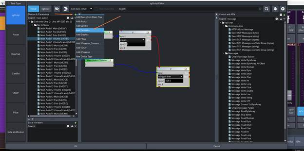
Then that would Add a Carbonite device which would allow you to set the IP address of Caprica or Companion then use the "rosstalk" API message and send a custom Message to those device or a GPI message to those devices to trigger them.
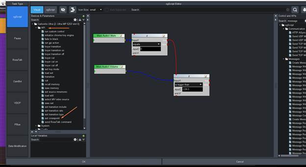
However – Back to how we can do this in the Ultra so we can use the TALLY connector on Ultra to do this.
On the Left side under our Carbonite Device there is an "API" section. This is to send RossTalk back to the device we are using for the data source. We will use the XPT command.
We are going to use Aux 28 as our "control bus" for the Tally. We are then going to use Aux 27 as a "source" that we can attach the Tally Too. Note this means we are kind of burning the use of Aux 27 and 28 as we need these for a way to use the ON AIR State and use the Source to turn the Tally on and OFF. If you had a source that is not in use you could use that source to attach the tally too but most people are not using all the Aux buses so this works well.
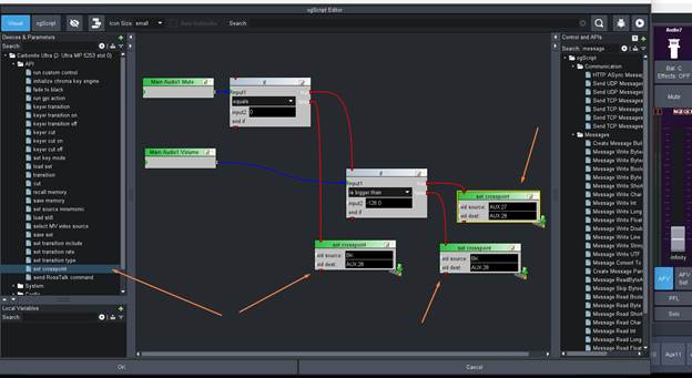
The Logic is built so that if MUTE is ON or if the Audio Level is -128 (infinity) the source on Aux 28 will be set to Black.
If Mute is OFF and the Audio is greater than -128 we will set Aux 28 to have Aux 27 as it's source.
We now need to apply the Same Logic (only I will place the first IF gate being the value of the volume) on the Mute button so that controlling the Mute Button will also trigger correctly based on those values.
Double click on mute and then add the following so it looks like this:
Now let's make sure we get the Context Focus
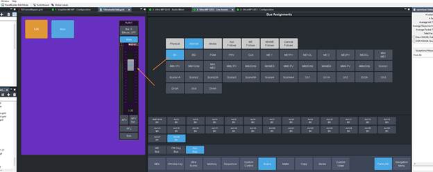
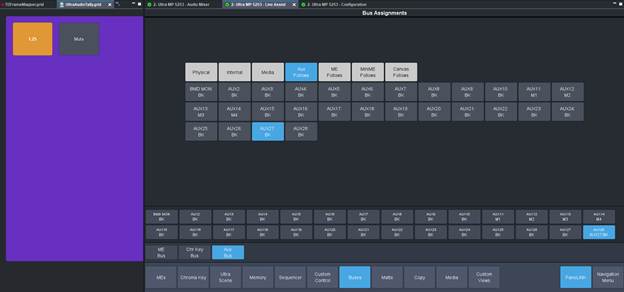
In Ultra Live Assist go to the Buses Tab and look at the Aux and Aux:28
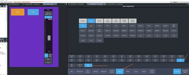
Now that you are here lets move the Audio Fader and play with the Mute button to see how the Panel changes sources Also at this time you can delete that Cut button from your panel:
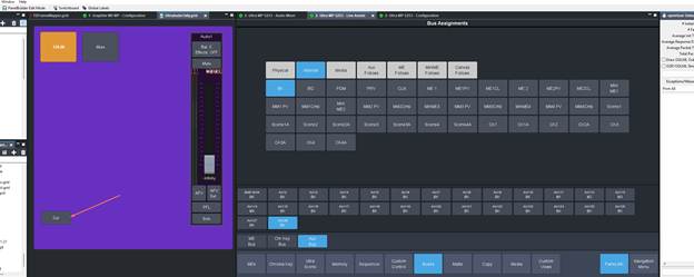
If I move the FADER off of infinity
We see the source change to input AUX:27
Now if we mute the Fader – we will see it go back to Black:

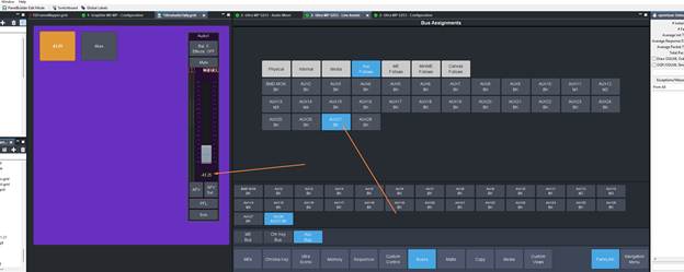
And if we move the Fader up to another level:
 It never switched from the Black as a source.. but if we now unmute it:
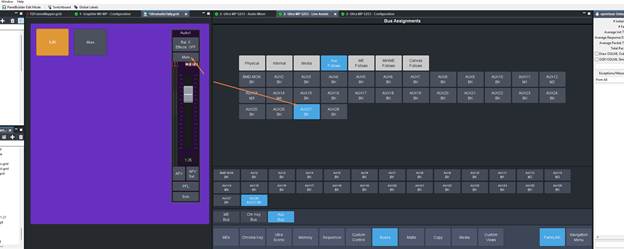
Back it goes to Aux:27.
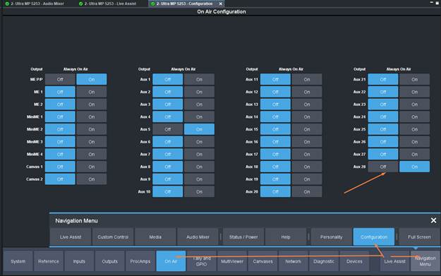
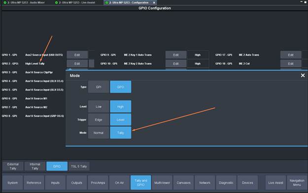
Now we just need to setup the Tally correctly in the configuration menus:
First we need to make Aux 28 "ON AIR" so that we can trigger Tally.
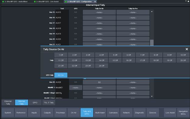
Now we to the Tally Menu, Internal Tally and scroll down to AUX 27. Now which ever pin you are wired up to using you can set that here
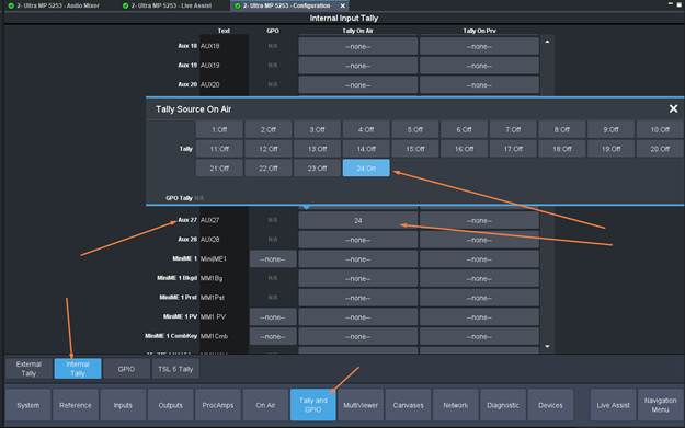
If your light source is not supplying the voltage and you need to send out 5v then you can instead configure a GPI as a GPO and set it to tally mode:
Now go back and it should be in the list to select for Aux 27 as well.
And at this point you do not need to keep that Fader Strip in the Custom Panel – you can remove it as well. Just makes it easier for testing when building out the panel.
This panel needs to be open in DashBoard for this to work.. you can not have this "closed".
So with this I have my "Audio Tally function".
------------------------------
Les O'Reilly
Director - Switcher Product Management
------------------------------